
Starlink Gen 3 Cables and Adapters: The Quick Answer
Starlink Standard hardware is often described by retailers as Gen 3 or V4. The kit uses a detachable, power-carrying Starlink cable with latching RJ45-style connectors between the antenna and Router 3. That familiar connector shape makes custom installations easier to plan, but the cable is not the same as an ordinary low-power Ethernet patch lead.
- Included cable: the current Standard kit specification lists a 49.2 ft (15 m) detachable cable.
- Router connectivity: Router 3 has two latching Ethernet LAN ports under removable covers, so many wired devices and third-party routers can connect without the separate Ethernet adapter used by some older Starlink kits.
- Outdoor pass-throughs: a weather-sealed bulkhead connector can create a neater cable entry through an RV, trailer, wall, or equipment enclosure.
- Extensions: use cable and connectors specifically suitable for the Starlink power load, shielding, outdoor exposure, and required total run. Starlink advises using kit-specific cable because the original assembly provides a locking, water-resistant seal and is power-rated for the system.
Before buying an adapter, confirm that you have the manually oriented Starlink Standard antenna and Router 3. Similar-looking Starlink generations use different cables, plugs, and power arrangements.
Identify Your Starlink Standard Kit First
The Starlink Standard antenna supplied with Router 3 is a flat rectangular unit with a removable kickstand and software-assisted manual orientation. During setup, the Starlink app guides you to a clear view of the sky and helps you align the antenna. It does not use the motorized mast found on the earlier Standard Actuated kit.
Router 3 uses Wi-Fi 6 and has two latching Ethernet LAN ports. The official specification lists compatibility with Starlink Gen 2 and Router 3 mesh nodes; it also notes that Starlink's native mesh system is not compatible with third-party mesh systems. You can still connect separate network equipment by Ethernet, but its routing, access-point, or bypass-mode setup depends on that equipment and the current Starlink app options.
If your antenna, router, or plug layout differs, identify the exact kit in the Starlink app or account before ordering cables or adapters.
How the Starlink Gen 3 Cable Works
The 49.2 ft (15 m) Starlink cable carries both data and power between the Standard antenna and Router 3. Its connectors resemble shielded RJ45 plugs, with latching features and seals designed for the Starlink hardware. Treat the antenna end as a powered outdoor connection, not as a conventional Ethernet-only socket.
For a reliable installation:
- Disconnect power before inserting, removing, or inspecting the cable.
- Seat each connector fully and preserve the original weather seal at the antenna and router.
- Avoid tight bends, crushed sections, sharp edges, standing water, and unsupported cable weight.
- Use UV-resistant, outdoor-rated cable protection where the run is exposed.
- Keep couplers and joins accessible for inspection rather than burying them inside an inaccessible wall or roof cavity.
Extending a Starlink Standard Cable
The lowest-risk approach is a Starlink cable length approved for your exact kit. If a custom extension or coupler is being considered, check the total conductor length, wire gauge, shielding, connector pinout, voltage drop, power load, and weather sealing as one system. A connector that fits physically can still cause intermittent faults, overheating, water ingress, or startup problems if the cable assembly is not suitable.
Do not assume that any indoor CAT6 cable or unshielded coupler is appropriate simply because it uses an RJ45-style plug. For exposed installations, every cable, gland, join, and enclosure must be rated for the environment. Browse our Starlink cables and accessories for purpose-built options, and check the listed hardware compatibility before ordering.
Weatherproof Bulkhead Connectors
A bulkhead connector provides a fixed pass-through point where the cable enters an RV, trailer, cabin, wall, or equipment box. This can reduce repeated pulling on the antenna cable and make setup or removal more convenient.
Our IP68 waterproof RJ45 bulkhead connector is designed for compatible Gen 3/Standard installations. The IP rating applies to the connector assembly when correctly installed; it does not make the entire cable route, wall penetration, or finished installation waterproof. Use the correct gasket, panel cutout, strain relief, and sealing method for the mounting surface.
Using the Router 3 Ethernet Ports
Router 3 includes two Ethernet LAN ports with removable covers. They can be used for wired computers, network switches, or a separate router or access point. This is different from the antenna cable port: the LAN ports are for normal network connections, while the Starlink port carries power and data to the antenna.
When adding third-party networking hardware:
- Use the Router 3 LAN port, not an inline join in the powered antenna cable.
- Choose whether the added device will act as an access point or router to avoid unintended double NAT.
- Confirm current bypass-mode instructions in the Starlink app before changing the network.
- Do not assume a third-party mesh unit becomes part of Starlink's native mesh; configure it according to its own manufacturer.
Power Considerations for Home, RV, and Off-Grid Use
The current Starlink Standard specification lists average system consumption of approximately 75–100 W, although actual demand varies with operating conditions and features such as snow melt. The supplied power equipment accepts 100–240 V AC. Size any inverter, battery, wiring, fusing, and DC conversion equipment for startup and peak demand rather than relying only on an average reading.
For 12 V, 24 V, or off-grid systems, a purpose-designed DC power supply can avoid the losses of converting battery DC to AC and back to DC. The converter must provide the correct output, power headroom, wiring protection, and connector arrangement for the exact Starlink kit. See our StarPower DC power supplies and accessories for compatible options and specifications.
Electrical work, roof penetrations, and permanent vehicle wiring should follow the applicable local codes and manufacturer instructions. Use a qualified installer where required.
Mounting and Cable Routing
The Standard antenna is manually oriented with guidance from the Starlink app. Select the location with the app's obstruction tool before drilling holes or committing to a long cable route. A clear sky view is more important than forcing the antenna into a convenient but obstructed position.
- Plan the route: measure the real path, including service loops, bends, and entry points.
- Protect the cable: avoid hinges, doors, exhaust heat, sharp metal, moving parts, and areas where cargo can crush it.
- Seal penetrations: use a suitable gland or bulkhead assembly and follow the sealant manufacturer's surface-preparation instructions.
- Provide strain relief: do not let cable weight or vibration load the antenna or router socket.
- Secure mobile hardware: the kickstand is for temporary placement. Use a mount designed for the antenna and installation surface, and secure or stow equipment before driving. Do not infer in-motion approval from the absence of motors.
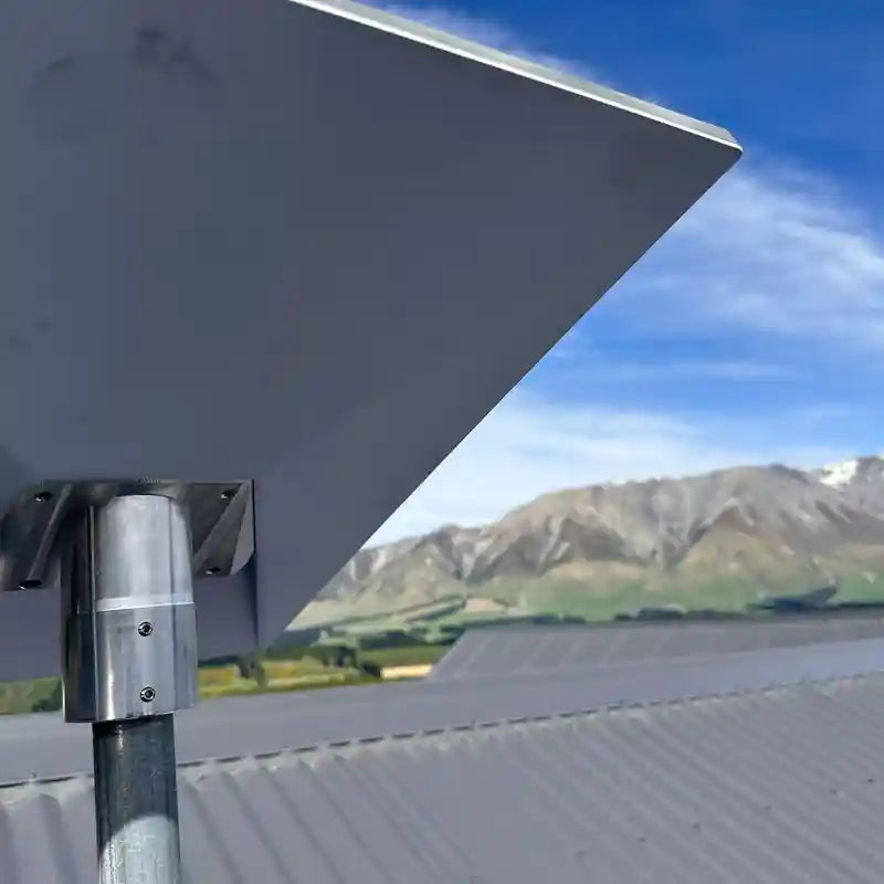
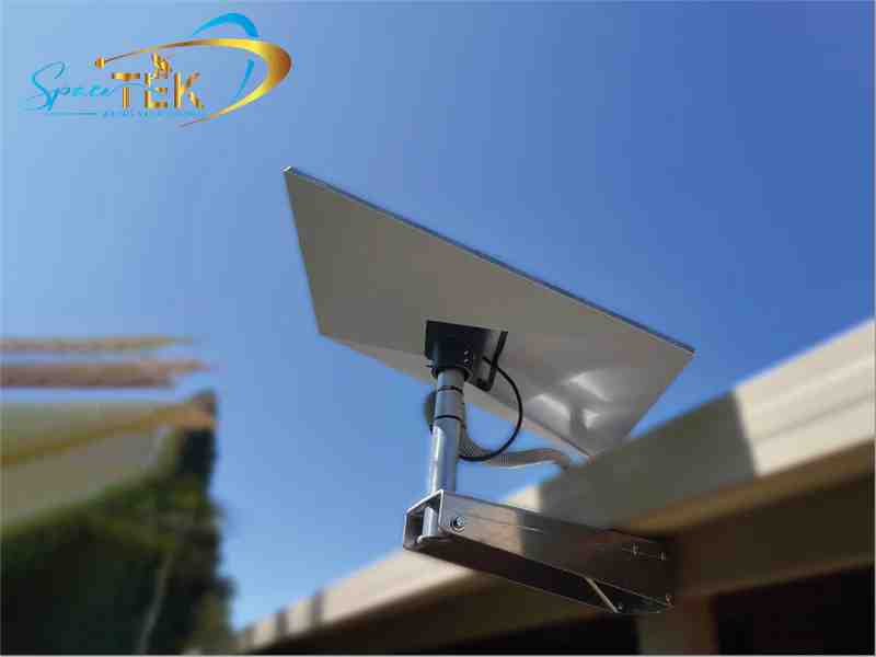
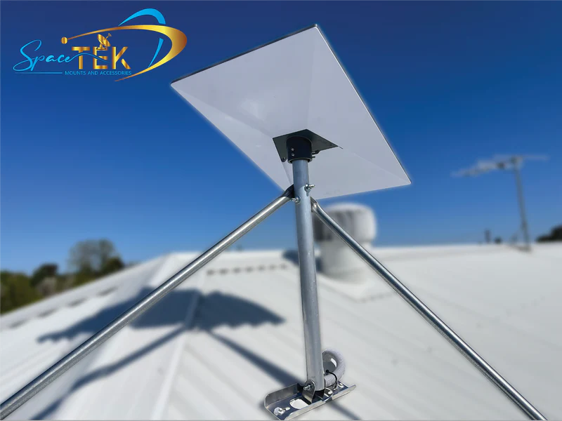
Explore Starlink Standard (Gen 3/V4) mounts and accessories for roof, wall, and pole installation options.
Cable and Adapter Checklist
- Exact Starlink kit and router confirmed
- Required cable length measured along the full route
- Powered antenna cable kept distinct from ordinary LAN cabling
- Shielding, conductor size, pinout, and power rating verified
- Outdoor joins protected from water, UV, and physical damage
- Panel penetrations sealed and strain-relieved
- Power source sized for the system, including startup and peak demand
- Mount and vehicle use matched to the manufacturer's current guidance and service plan
Build a Reliable Starlink Standard Installation
Starlink Standard's detachable cable and Router 3 Ethernet ports make the system more flexible than earlier proprietary-cable setups, but dependable results still come from treating power, data, weather sealing, and mechanical protection as one installation.
Choose adapters for the exact hardware, plan cable lengths and connection points deliberately, and avoid generic extensions that have not been checked for the Starlink power load. If you need help matching a cable, connector, mount, or DC supply to your setup, contact Spacetek with a photo of the antenna, router, and connector ends.

Leave a comment
This site is protected by hCaptcha and the hCaptcha Privacy Policy and Terms of Service apply.